1 Anuduino
Contents
- 1 Anuduino
- 2 How to programme your chip
- 3 USB Connections
- What is arduino?
Arduino is an open-source electronics prototyping platform. It’s intended for artists, designers, hobbyists and anyone interested in creating interactive objects or environments but that too expensive ($15) for small projects or if you are new to electronics.We started exploring Digispark project which has developed around 9$ ATtiny-85 Arduino compatible board. We have redesigned the circuit with optimized components and used DIP packages and single sided PCB to reduce cost to less than 3$.
- Why anuduino ?
It is micro-sized, Arduino enabled, usb development board - cheap enough to jumpstart electronics. It is easy to make Do It Yourself project either using its kicad files or on breadboard.
- Difference between arduino and anuduino ?
ArduinoUNO uses ATmega328 microcontroller with 32Kb of flash memory of which 5Kb is used by the bootloader whereas anuduino has 8Kb of flash memory with 2Kb occupied by bootloader,so you have around 6Kb of memory left for code.
Memory Anuduino ArduinoUNO Flash(Total) 8k bytes 32k bytes Flash(Bootloader) 2k bytes 5k bytes Static RAM 512 byte 2k bytes EEPROM 512 byte 1k byte
PINS Anuduino ArduinoUNO Total 8 32 Total I/O 6 23 Digital I/O (PWM) 6 (3) 16 (6) Analog I/O 4 6
Note
The above comparison is made with Arduino UNO which is a pretty common.There are other variants of Arduino with more cost, more memory and features as well.
- What is Anuduino ?
- Anuduino is an ATtiny85 based microcontroller development board with USB interface.
- It uses the familiar Arduino IDE for development.
- PWM on 3 pins
- ADC on 4 pins
- I²C and SPI (vis USI)
- 6 I/O pins (2 are used for USB only if your program actively communicates over USB, otherwise you can use all 6 even if you are programming via USB)
- 8 KB flash memory (about 6 KB after bootloader)
- How micronucleus bootloader works ?
Micronucleus is a bootloader designed for AVR tiny 85 chips with a minimal usb interface.Micronucelus is the code that is installed on the device using an avr programmer. This code allows the anuduino to act like a USB device, receives code, and when it receives code erase the code previously loaded. It also runs the code loaded onto it after a 5 second delay (if bootloader uploaded is normal version , more about this later) if it does not receive a request to upload new code within that 5 seconds.
It is a small V-USB program, similar to the DigiUSB, DigiKeyboard, and other usb related libraries. Normally programs exist at the very beginning of the flash memory in the attiny85 chip, but micronucleus has been modified so the start of the program is about 6kb of 0xFF bytes (In other words all the bits in 6Kb are high). After that, micronucleus begins and uses up the final 2kb. This leaves room at the start of the chip for your own programs, but micronucleus always stays installed at the end. 0xFF bytes are interpreted as NOP (no operation) instructions by the AVR chip, so the first time you run it, or if you run it after an erase but no write (sometimes this happens if there is an error during the erase part of an upload attempt), next time the chip turns on it will execute all those NOPs and slam in to the bootloader code.
When you use micronucleus to upload a program, there’s a trick to it - USB requires the device always respond to requests, but the tiny85 chip can’t do that - whenever it’s erasing or writing part of it’s own program memory it has to go to sleep for about 4.5 milliseconds. Some of the more expensive chips like the mega328 have special bootloader support which lets them keep running in the background while an erase or write happens in another section of memory. Embedded Creations discovered however that if you craft your computer program to just not send any requests during that frozen time, the computer never notices the device has frozen up and doesn’t crash the USB connection. This is pretty fragile, which is why the USB connection to the bootloader can sometimes crash if you run other intense usb software in the background, like an instance of digiterm polling for a device to appear.
So when the micronucleus command line tool first finds anuduino, it asks it “How much memory do you have, and how long should I wait after each type of request?” - when you see that assertion fail on ubuntu, it’s talking about that request - the program tried to ask that question and had an error response due to linux permissions issues. Next,it asks the device to erase it’s memory and waits the right amount of time for it to do so - about 50 milliseconds to do all 6kb of flash pages. Once that’s done, it starts uploading 64 byte chunks of your new program. Micronucleus writes in these bytes at the starting 6kb of flash memory, but with one special exception:
In the first page there’s an interrupt vector table. The bootloader (on the device) replaces the reset vector and the pinchange vector with jump instructions pointing to it’s own interrupt vector table 6kb later. Other than that, the program is left alone. When the computer is finished uploading, the bootloader finally writes down what the original values of the user’s reset vector and pinchange vector were in the very last four bytes of that first 6kb chunk of blank memory.
This little modification ensures the bootloader will run first when the chip is powered, and the pinchange interrupt is necessary for V-USB on the device to function in the bootloader. But wait - the user program needs to be able to use the V-USB to talk over USB as well! Embedded Creations came up with a really neat solution for that in their USBaspLoader-tiny85 project: Whenever the bootloader is running a special part of memory contains 0xB007 - whenever the pin change interrupt handler function is run inside of the bootloader, it checks if those two bytes are there, and if not, it immediately jumps to the user program’s pinchange handler. This detect and jump behaviour is fast enough to not cause any problems with the V-USB software, but does mean other programs using PCINT (pin change interrupt) on the anuduino will find there’s a slightly longer delay before their function runs than there is on a raw chip with no bootloader.
For more information on the tricks micronucleus uses to add a bootloader on a chip with no built in bootloader features, check out embedded-creations USBaspLoader-tiny85 site
- At what clock speed and voltage level does the circuit work?
It uses the high speed PLL at 16MHz.The internal PLL of Attiny85 generates a clock frequency that is 8x multiplied from a source input. By default, the PLL uses the output of the internal, 8.0 MHz RC oscillator as source and the safe voltage is 3.8V or more for this speed. 16.0 Mhz is more useful with existing arduino libraries. Also if you Run the attiny85 at < 4V you might even brick it. That puts the chip out of specifications and the results are unpredictable ,sometimes the bootloader will overwrite bits of itself and brick the device requiring a high voltage serial programmer (or regular ISP programmer if you didn’t disable the reset pin) to recover.Hence it’s suggested to use 5V supply.
- What if my code is more than 6 K?
If you are uploading your sketch using Digispark integrated Arduino IDE ,before uploading if you compile the code you will get an idea of how much memory does your code need.So before uploading its a good habit to first compile your code.In case it’s more than 6kb it’s likely to overwrite your bootloader.In which case you have to reflash the bootloader using ISP programmer.But you can reupload the bootloader on your chip only if your reset pin is disabled as I/O (reset HIGH).In case your reset is enabled as I/O you will need HVSP (High volt serial programmer) to reconfigure your chip to be programmed with ISP programmer.Tersely ,it’s a matter of fuse settings (specifically the RESET bit of hfuse) of your chip.
- Can I use it in other OS ?
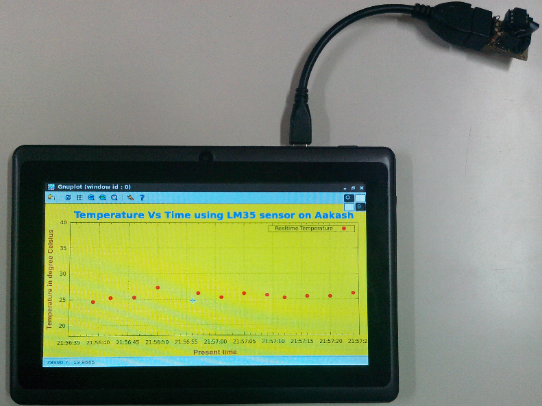
It can be used on GNU/Linux, Aakash tablet running on Ubuntu-12.10 ARM version,and various others. This tutorial is dispositioned more towards GNU/Linux users.
- What all can it do ?
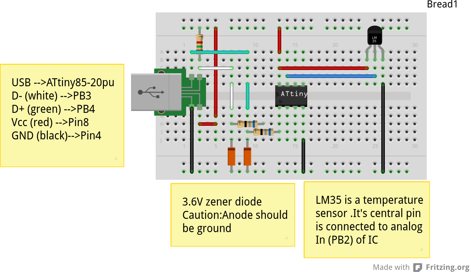
It can be integrated with number of sensors (IR, proxomity, temperature) , bluetooth module,as a multimeter etc.
- How serial communication occurs ?
The anuduino does not have a hardware serial port nor a hardware serial to USB converter. V-USB is a software-only implementation of a low-speed USB device for Atmel’s AVR microcontrollers, making it possible to build USB hardware with almost any AVR microcontroller, not requiring any additional chip for serial conversion. Bluebie wrote the micronucelus bootloader which uses the V-USB project and renders anuduino to be used as usb development board without need of any additional chip.
- What is hex file ?
A hex file is a way to store data, in this case compiled code for an avr microcontroller. It is a common file format and something being a hex file does not mean it can be uploaded on the chip. When you use the Arduino IDE to upload a file to the board your code is compiled into a hex file and then uploaded using the command line tool which is built into Arduino.
- Whats is cdc232.hex ?
cdc232 is a version of this project, Bluebie, the maker of micronucleus included this in the micronucleus repository for people who might want it - basically it makes a anuduino into a cheap USB to serial converter.It’s just like any other sketch or hex file and will be overwritten if you upload any other sketch say Blink.hex.
- If you upload sketches with DigiUSB libraries it detects as USB-HID(Human Interface Device)?
It’s ok if the anuduino doesn’t detect as ttyACM device ,in general if a device detects as tty device it means it is a USB-serial device.But anuduino in not a USB-serial device ,it does not provide USB-serial interface. So when you plug your anuduino ,the serial port tab of digispark integrated arduino IDE will be greyed out.(link to the IDE is given below under the heading pre-requisite packages).
DigiUSB - Debugging and HID communication library On the computer side you can use the included command line tools in the DigiUSB Programs folder available in the Integrated IDE: digiusb - this program is like the Arduino serial monitor, allowing you to send and receive messages to/from a Digispark running DigiUSB
If you upload a sketch with digiusb libraries then you can see it as HID device , do
ls /dev/usb/hiddev0
1.1 Hardware requirement to build the project
All you need is:
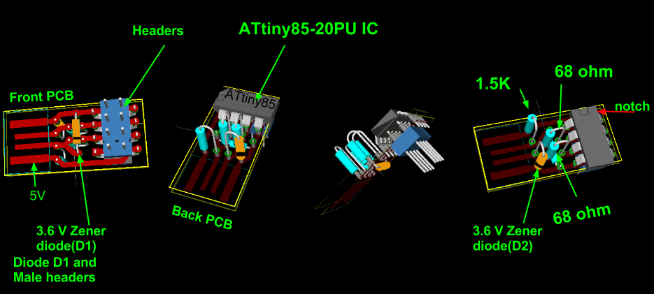
One Attiny85-20PU
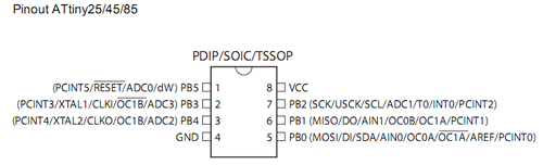
Atmel’s ATtiny85 8-Bit Processor. 8K of program space, 6 I/O lines, and 4-channel 10 bit ADC.
Warning
Make sure your ATtiny85 is the 20 variety (ATtinny85-20PU),and not an ATtiny85-10PU. The v version is low voltage and totally out of spec for USB stuff like the micronucleus bootloader.
Two 3.6V Zener Diode
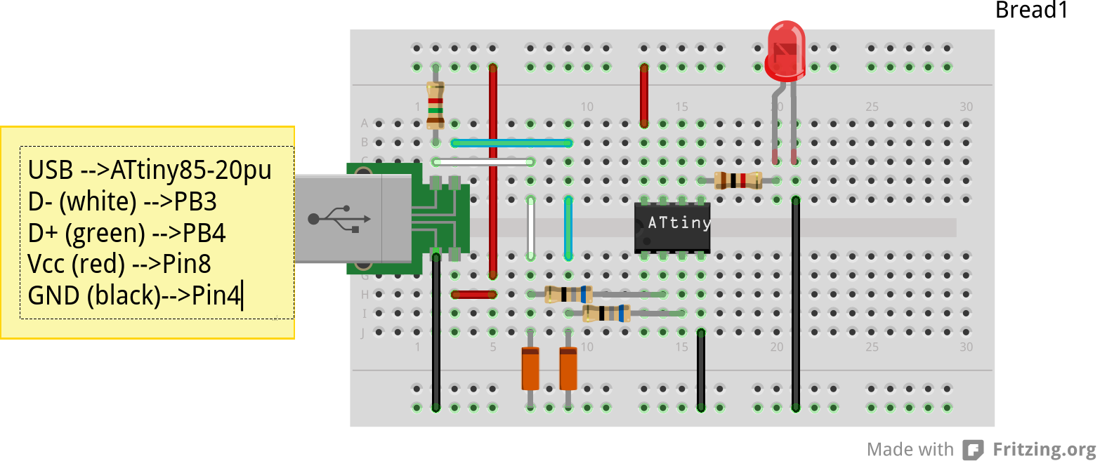
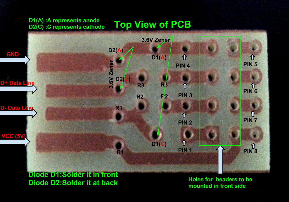
Zener diodes:Power rating is critical .Most of the time it’s perfectly safe to overrate your parts and use a component with a higher rating than required for this particular circuit. However, in this case that approach can actually prevent the circuit from working because the trade-off in Zener diode design is that as its power rating increases it also exhibits more capacitance. Capacitance on a high-speed data line is very bad and needs to be avoided or the circuit simply won’t work. In practice, a 1/4W Zener should work fine; a 1/2W Zener should work, but is a bit on the borderline; and a 1W Zener almost certainly won’t work it will have too much capacitance. It’s a simple circuit, USB socket gets its +5V power line from the usual place, and the 3.3V data lines use three resistors and two 3.6V 1/4W Zeners to reduce the Arduino’s 5V to 3.3V.Purpose of zener diode is essential for the circuit.Even though the power supply line is 5v,communication line work at nominal 3.3V.The D- and D+ lines are dependent signalling lines unlike tx ,rx in RS232 .They are half duplexed differential signalling pair helping the USB to run at high data speeds by reducing the effects of electrical noise.
While assembling my circuit I used 4.8V instead of 3.6V zener, without doubt I got error(2) message. Check below error(2).
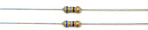
Three resistors
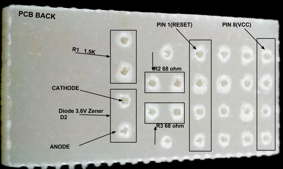
- 1x1.5K ohm
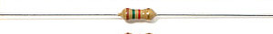
Not just a faulty diode value can drive you crazy,for your board won’t detect ,resistor can be the culprit too.Like in case by chance you use 15k instead of 1.5k ,wondering how,its just a matter of seeing red band as orange and orange as red in super excitement may be.Ya ,I made this terrible mistake too. Learn from it.Many people have used 1.8K and few nearby resistor values so just in case you are short of 1.5k then you might use other values without much ado.
- 2x68 ohm
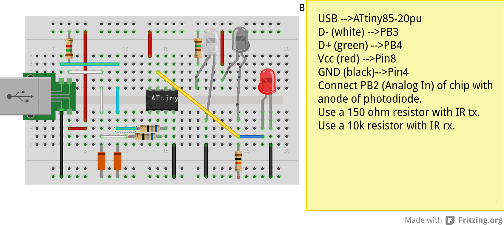
Broken USB-A cable if you don’t have the PCB and you plan to make it on a breadboard.
For KICAD files click this link
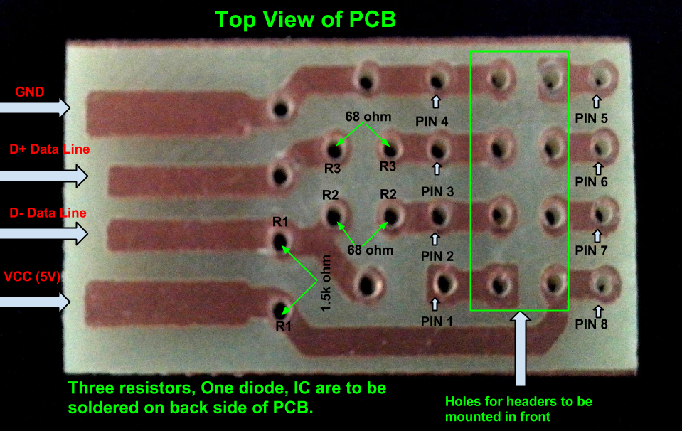
note: The anode side of both diode is grounded and cathode side is connected to data lines
2 How to programme your chip
2.1 Pre-requisite packages
- arduinoIDE Arduino IDE to use arduino-UNO as ISP to flash bootloader and set fuses of ATtiny85 chip.
- Bootloader This repository contains the source of bootloader to be flashed on ATtiny85.
- DigisparkIDE ArduinoIDE integrated with Digispark libraries is required to run programs on your DIY project Anuduino.
It also contains all the tools needed to programme your chip including avrdude binary and micronucelus binary.
Note
Note all the possible errors you might encounter while assembling your circuit are given below under errors heading.
2.2 Arduino as ISP
- arduinoIDE Arduino IDE 1.04 version to use arduino-UNO as ISP to program your ATtiny85 chip.
- Plug in your arduino board
- File–>Examples–>ArduinoISP
- Tools–>Board–>Arduino UNO
- Tools–>Serial Port–>/dev/ttyACM*
- Upload the sketch on your arduinoUNO.
- Now you can use it to burn bootloader on your Attiny85 chip.
- ArduinoISP Tutorial
2.3 Programming ATTiny85 with Arduino
- ArduinoUno uses SPI protocol .To knpw more on this click here
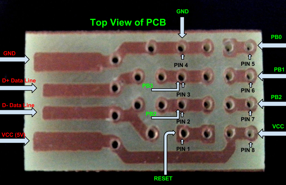
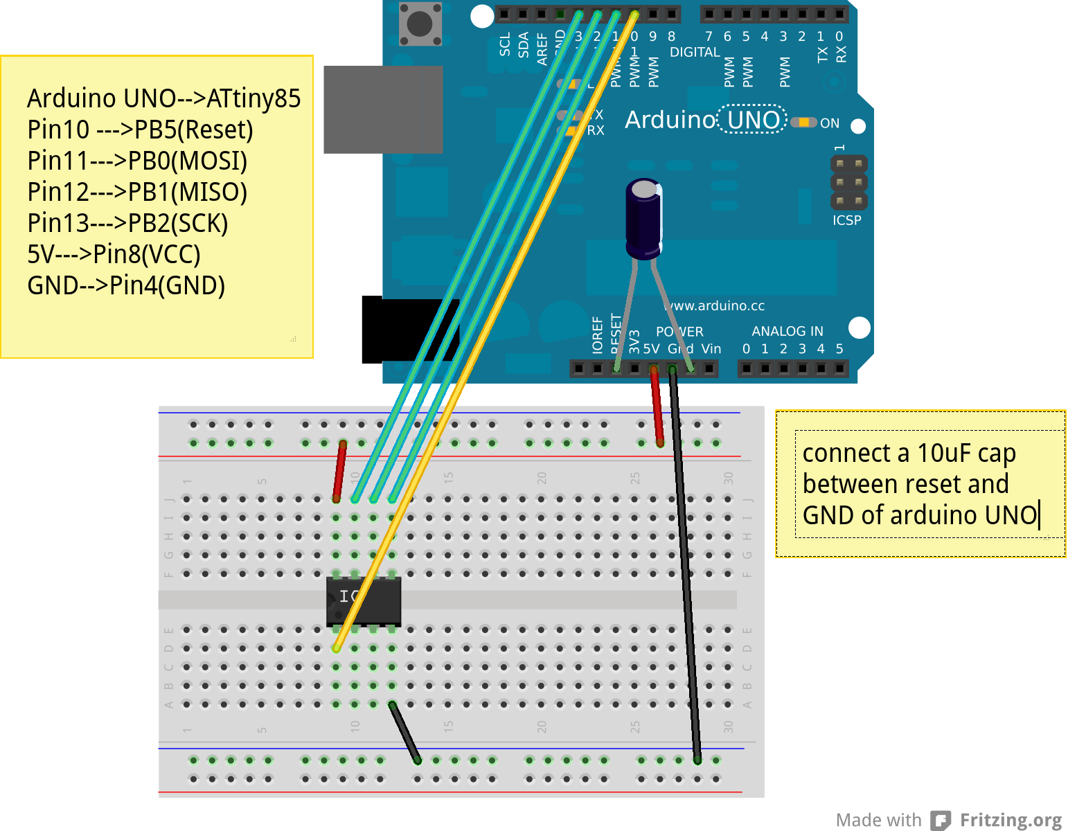
Make the following 6 connections on your breadboard between ArduinoUNO and ATtiny85-20PU.Make sure your connections are firm. Improper connections is the major issue generating errors.
RECHECK CONNECTIONS
PINS Attiny85 ArduinoUNO MOSI PB0 11 MISO PB1 12 SCK PB2 13 RESET PB5 10 VCC Pin8 5V GND Pin4 GND
Warning
If you are programming with Arduino UNO then use a 10uF capacitor between RESET and GND of arduino UNO.
Next CHECK if you have made proper wired connections between Arduino UNO and ATtiny85 chip prior to burning bootloader or setting fuses of your chip .
For this your need avrdude binary and avrdude.conf file which is available in the package Digispark Integrated Arduino IDE (available here )
- cd to the directory DigisparkArduino-Linux32/Digispark-Arduino-1.0.4/hardware/tools/
Here you will find the avrdude and avrdude.conf file
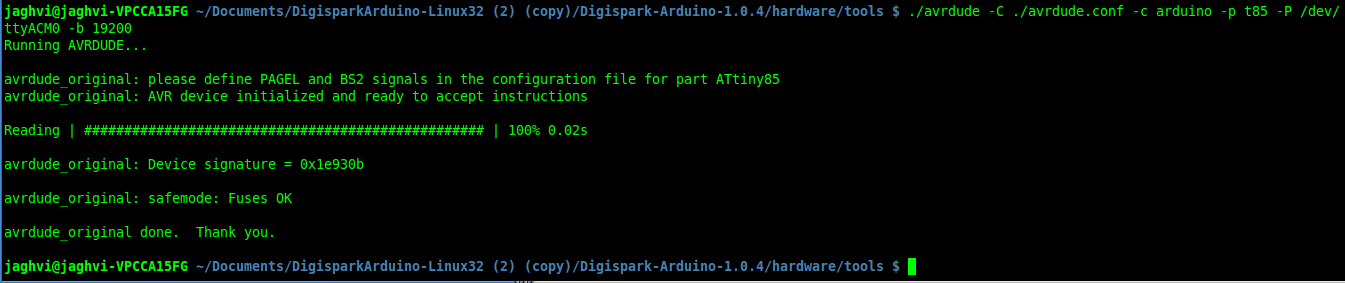
Next run this command in terminal and see that the device signature matches that of Attiny85 (0x1e930b).
./avrdude -C ./avrdude.conf -b 19200 -c arduino -p t85 -P /dev/ttyACM0
Note
change the port to your port /dev/ttyACM* or /dev/ttyUSB* or you might get errors.
2.4 Burning micronucleus.hex and setting fuses
- Download the following repository which contains the micronucelus bootloader.
2.4.1 Uploading BOOTLOADER
Before you start anything ,there are two versions of bootloader.
- First (NORMAL) is : micronucleus-1.06.hex .In this version there is a 5 seconds delay prior to execution of already uploaded sketch.Within this 5sec the anuduino checks whether you have a new programme to overwrite already existing programme on the chip or if not it starts the programme already uploaded after a 5 seconds delay.For eg: say you had programmed your chip to blink led on PB0. Now if you plug in your device after some time, it will take 5 seconds for your led to start blinking.
- Second (JUMPER) : Now if every second is crucial to your project and you can’t wait for your programme to start after 5 seconds ,there is this another version micronucleus-1.06-jumper-v2-upgrade.hex
Bootloader is already available in the IDE you downloaded .It is in the DigisparkArduino-Linux32/DigisparkArduino-1.0.4/hardware/digispark/bootloaders/micronucleus/ folder or you can also obtain the latest version from micronucelus-t85 repository.
2.4.1.1 Uploading the NORMAL version
Note
change the paths in the following commands within quotes(” ”)to where your downloaded IDE folder exists.
cd to the directory DigisparkArduino-Linux32/Digispark-Arduino-1.0.4/hardware/tools/ Here you will find the avrdude and avrdude.conf file
Next run this command in terminal (This will upload the bootloader already available in the ArduinoIDE
./avrdude -C avrdude.conf -P /dev/ttyACM0 -b 19200 -c arduino -p t85 \
-U flash:w:"/home/DigisparkArduino-Linux32/Digispark-Arduino-1.0.4\
/hardware/digispark/bootloaders/micronucleus/micronucleus-1.06-upgrade.hex"
This will burn the bootloader on your chip.
Next step is to set appropriate fuses.
2.4.1.2 Uploading the JUMPER version
Use the latest version of this bootloader available at micronucelus repository.You can also copy the bootloader hex file from here and paste it in the IDE’s bootloader folder to keep track.
Upload micronucleus1.06-jumper-v2.hex from micronucelus-t85/firmware/releases folder.
Set path in the following command to where your bootloader hex file is located.
./avrdude -C avrdude.conf -P /dev/ttyACM0 -b 19200 -c arduino -p t85 -U \
flash:w:"/home/micronucleus-t85-master/firmware/releases/micronucleus-1.06-upgrade.hex"
2.4.2 Setting fuses of the attiny85-20PU
Now just like bootloader versions we have two different fuse settings as well
First In this case you can still programme your chip using ISP programmer but you will have just 5 I/O excluding the reset pin(reset pin disabled as I/O). These fuse settings won’t work with Jumper version of bootloader.Jumper version requires a jumper between the resest pin and GND to upload the programme.
Second In which there are 6 I/O pins available including reset pin (reset pin enabled).You get 6 I/O but at a cost that you can’t reprogramme your chip using any ISP programmer now. You will need a HVSP. You can use this setting for both bootloader versions ,Normal as well as Jumper version. Reset Pin acts as weak (I/O).
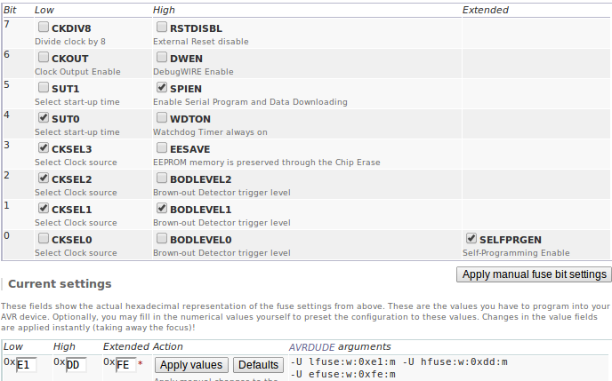
2.4.2.1 Fuse setting(Reset disabled as I/O)
Note
These fuses setting will not enable reset pin (ATTINY85 pin 1) as I/O, so you only have 5 I/O instead of 6 I/O
- cd to the directory DigisparkArduino-Linux32/Digispark-Arduino-1.0.4/hardware/tools/
Here you will find the avrdude and avrdude.conf file
Run the following command in terminal
./avrdude -C avrdude.conf -p t85 -c arduino -P /dev/ttyACM0 -b \
19200 -U lfuse:w:0xe1:m -U hfuse:w:0xdd:m -U efuse:w:0xfe:m
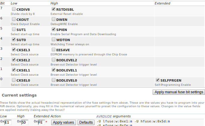
2.4.2.2 Fuse setting(Reset enabled as I/O)
Warning
If you use the above fuse settings you can’t reprogramme your IC until you have a High volt fuse resetter .This is because reset pin is enabled as I/O and you can’t programme it using ISP.
Set fuses to enable the reset pin to be used as I/O lfuse:0xe1 hfuse:0x5d efuse:0xfe
cd to the directory DigisparkArduino-Linux32/Digispark-Arduino-1.0.4/hardware/tools/. Here you will find the avrdude and avrdude.conf file.
Run the following command in terminal
./avrdude -C avrdude.conf -p t85 -c arduino -P /dev/ttyACM0 -b 19200 -U\
 lfuse:w:0xe1:m -U hfuse:w:0x5d:m -U efuse:w:0xfe:m
Now if you are done with the above two steps (burning bootloader and setting fuses) you are ready to upload sketches.
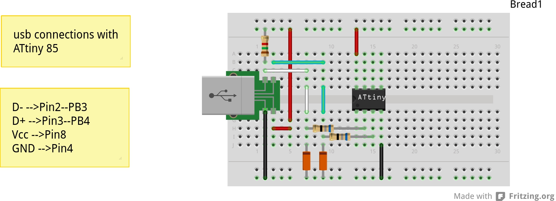
After the above two steps are accomplished ,make the following USB connections (only if you don’t have your own PCB) and follow the next step.
3 USB Connections
3.1 Device Detection
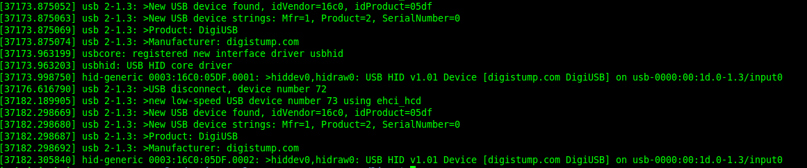
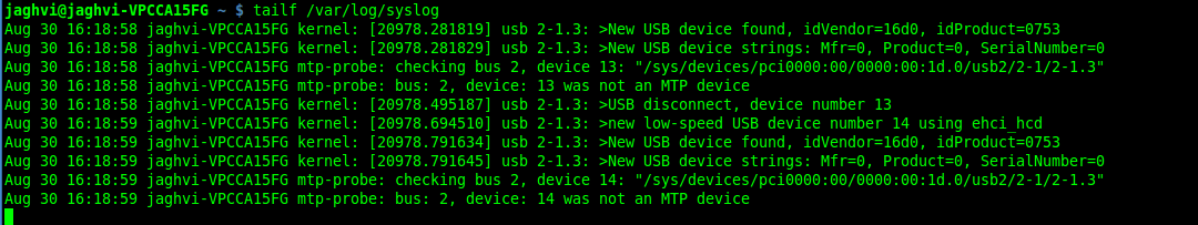
- A vendor ID is necessary for developing a USB product.
run command dmesg or tailf /var/log/syslog in terminal to check the vendorID and productID
3.2 Setting rules in udev to avoid assertion errors
Go to /etc/udev/rules.d/ with root privileges.
gedit 49-micronucelus.rules and add the following lines
SUBSYSTEMS=="usb", ATTRS{idVendor}=="16d0", ATTRS{idProduct}=="0753",\
MODE:="0666"
KERNEL=="ttyACM*", ATTRS{idVendor}=="16d0", ATTRS{idProduct}=="0753",\
MODE:="0666", ENV{ID_MM_DEVICE_IGNORE}="1"
Also add 99-digiusb.rules in /etc/udev/rules.d/
gedit 99-digiusb.rules and add the following lines
KERNEL=="hiddev*", ATTRS{idVendor}=="16c0", ATTRS{idProduct}=="05df", SUBSYSTEM=="usb"For more info visit Udev rules setting
3.3 Uploading Programme
- DigisparkIDE ArduinoIDE integrated with Digispark libraries is required to run programs on your DIY anuduino project.
3.3.1 Normal Version of Bootloader
- Board—>Digispark(TinyCore)
- Programmer—>Digispark
Note
DO NOT plug the device until asked
- Click Compile the code to check if the code exceeds 6Kb.
- Click Upload (IDE will ask to plug int the device within sixty seconds)
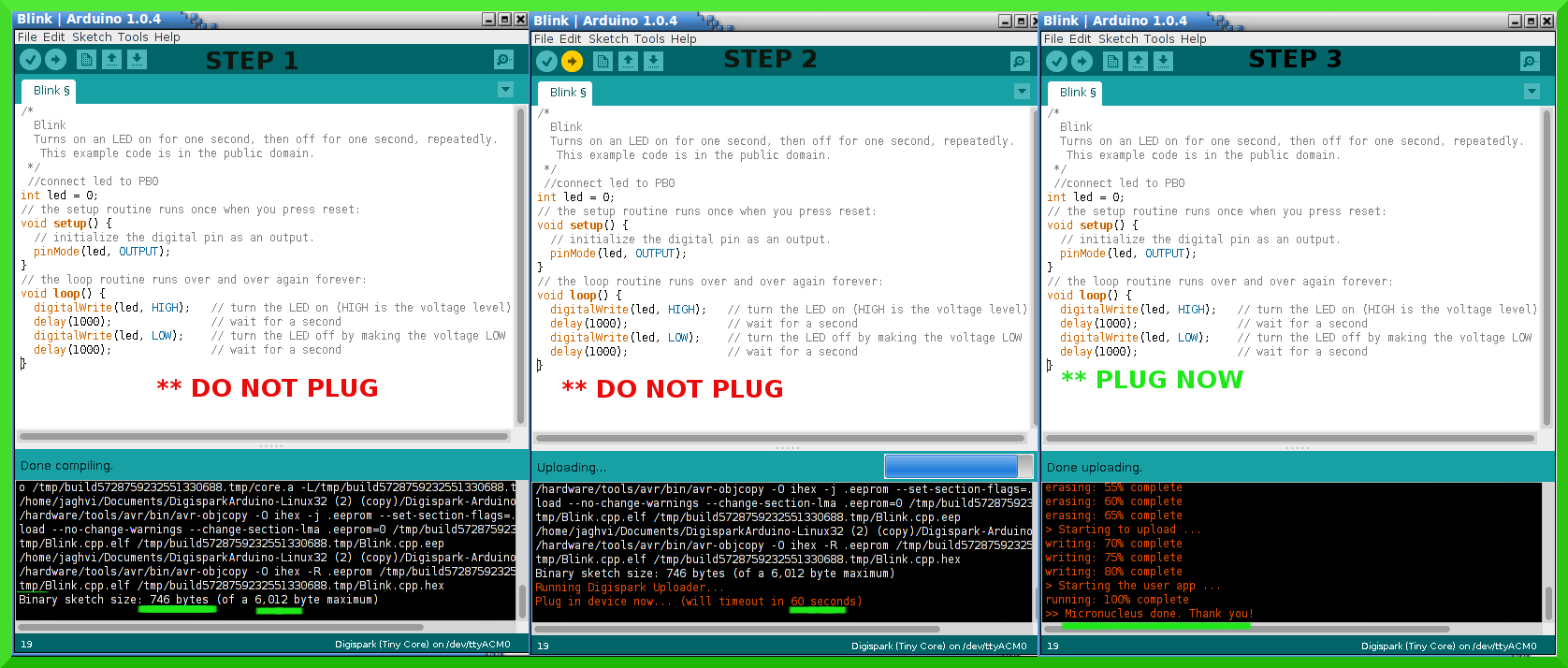
- Now Plug anuduino
- If upload was not successful then you will get error message.Try to repeat the process.
3.3.2 Jumper Version of Bootloader
- Jumper version removes 5 sec delay.
- Board—>Digispark(TinyCore)
- Programmer—>Digispark
- Upload (IDE will ask to plug int the device within sixty seconds)
- Connect PB5(Reset) to GND using a jumper if you need to upload sketch.
- Plug anuduino
- If successful deplug your device, remove the jumper wire between reset pin and GND, and replug the device, Your programme will start executing instantaneously without 5 seconds delay.
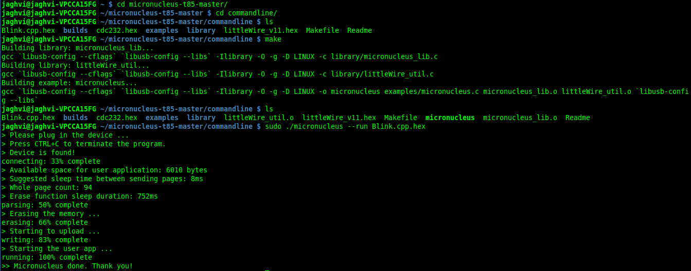
3.4 Uploading from commandline
How to use the micronucelus command line tool:
- You can either use the micronucelus binary already available in the Digispark-Arduino IDE which you must have already downloaded by now.
Go to DigisparkArduino-Linux32/Digispark-Arduino-1.0.4/hardware/tools folder and run the following command in terminal
sudo ./micronucleus --run Blink.hex
or if your hex file is stored elsewhere then
sudo ./micronucelus --run /home/jaghvi/program/Blink.hex
OR you can
Download micronucelus-t85 folder from github (you might have this already ,micronucelus bootloaderhex files were used from this repo)
In that folder go to commandline folder and do make
A micronucelus binary is formed.
You can see micronucelus –help to know all the options.
Run the following command to upload the hex file.
sudo ./micronucleus --run Blink.hex
If you get this error try to run it again
>> Abort mission! -32 error has occured ...

>> Please unplug the device and restart the program.
3.4.1 Burn cdc232.hex
To enumerate anuduino as USB serial device run this command
sudo ./micronucleus micronucleus-t85-master/commandline/cdc232.hex
run command dmesg in terminal to enumerate the device as /dev/ttyACM*
3.5 ERRORS encountered
3.5.1 Error when using ISP programmer
Note
All the errors encountered in avrdude are mainly due to poor connections between ISP programmer and ATtiny85 Redo your connections and see that no wire is loose.
Error
This error occurs as your arduinoUNO might be on a serial port other than /dev/ttyACM0
avrdude: ser_open(): can't open device "/dev/ttyACM0": No such file or directory
ioctl("TIOCMGET"): Invalid argument
Avrdude output
avrdude: please define PAGEL and BS2 signals in the configuration file for part ATtiny85
avrdude: AVR device initialized and ready to accept instructions

Reading | ################################################## | 100% 0.02s

avrdude: Device signature = 0x000000
avrdude: Yikes!  Invalid device signature.
         Double check connections and try again, or use -F to override
         this check.
Error
Note
If baud rate is note set properly then stk500 error is encountered.
This error also occours if capacitor is not used in case you are programming with Arduino UNO.
avrdude: stk500_getparm(): (a) protocol error, expect=0x14, resp=0x14

avrdude: stk500_getparm(): (a) protocol error, expect=0x14, resp=0x01
avrdude: stk500_initialize(): (a) protocol error, expect=0x14, resp=0x10
avrdude: initialization failed, rc=-1
         Double check connections and try again, or use -F to override
         this check.
Error
avrdude: stk500_getsync(): not in sync: resp=0xe0
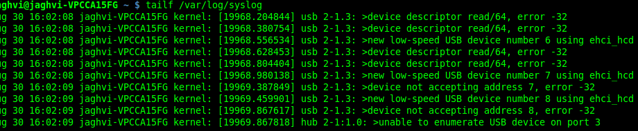
3.5.2 Errors while making USB connection
Error
Run dmesg or tailf /var/log/syslog .Following error might occur due to number of reasons.If you have used a faulty resistor value or if the zener diodes used are of values other than 3.6V. Check if all the connections are proper specially consulting D- and D+ lines.
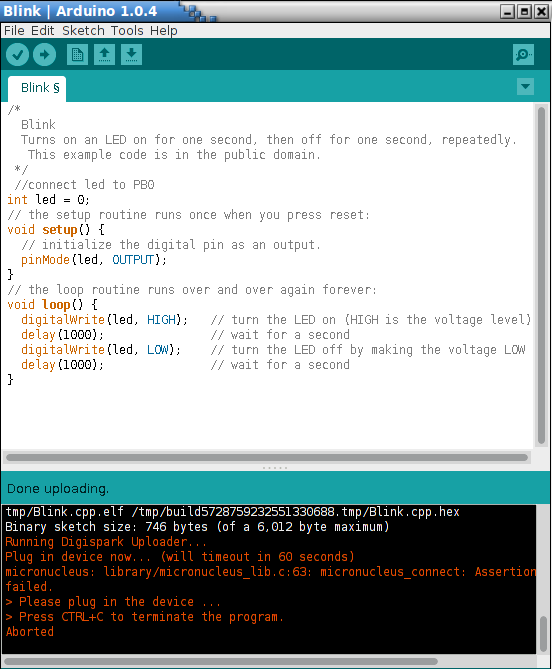
Error
Bad permissions generally cause the
Abort mission! -1 error has occured ...
>> Please unplug the device and restart the program.
“micronucleus: library/micronucleus_lib.c:63: micronucleus_connect: Assertion ‘res >= 4’ failed.” is also a result of bad permissions.
So set the required rules in /etc/udev/rules.d/ as explained above to avoid these errors. Linux troubleshooting
3.6 Serial Monitor
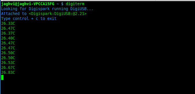
You can either use Digisparks official monitor or use Bluebie’s digiterm written in ruby.
3.6.1 Digiterm
Digiterm: It is a Serial Monitor written in ruby.You need certain packages to install it.Click this link to know more.
To install digiterm do
gem install digiusb
3.6.2 DigiUSB monitor
- The Digispark integrated arduinoIDE has DigiUSB libraries which has the DigiUSB monitor working like a serial monitor.
DigiUSB monitor has two more binaries send and receive.
- send - this allows you to send data/text to your board with DigiUSB - run with –help to see all options
- receive- this allows you to receive data/text from your board(anuduino) with DigiUSB - run with –help to see all options.
See the DigiUSB→Echo example and the applications in the “Example Programs” folder for an example of how to use the DigiUSB library.
To output your data in a text file run the receive binary using this command
$ ./receive >> output.txt